Alphabetical Index
Chemical Composition of Steels
Keyword Search
Steel Names
Alloyed Steels
Carbon Steels
Cast Irons
Chromium Steels
Cold Work Tool Steels
Creep Resistant Steels
Hot Work Tool Steels
Molybdenum Steels
PM steels
Stainless Steels
Structural Steels
Tool Steels
Vanadium Steels
White Cast Irons
M2C Carbides
M3C Carbides
M7C3 Carbides
M23C6 Carbides
MC Carbides
Light Microscopy
EDS/WDS Microanalysis
Scanning Electron Microscopy
Transmission Electron Microscopy
X-Ray Diffraction
Help
Contact Us
Home
Mo2C and Fe3C carbides in FeCMo martensitic steel
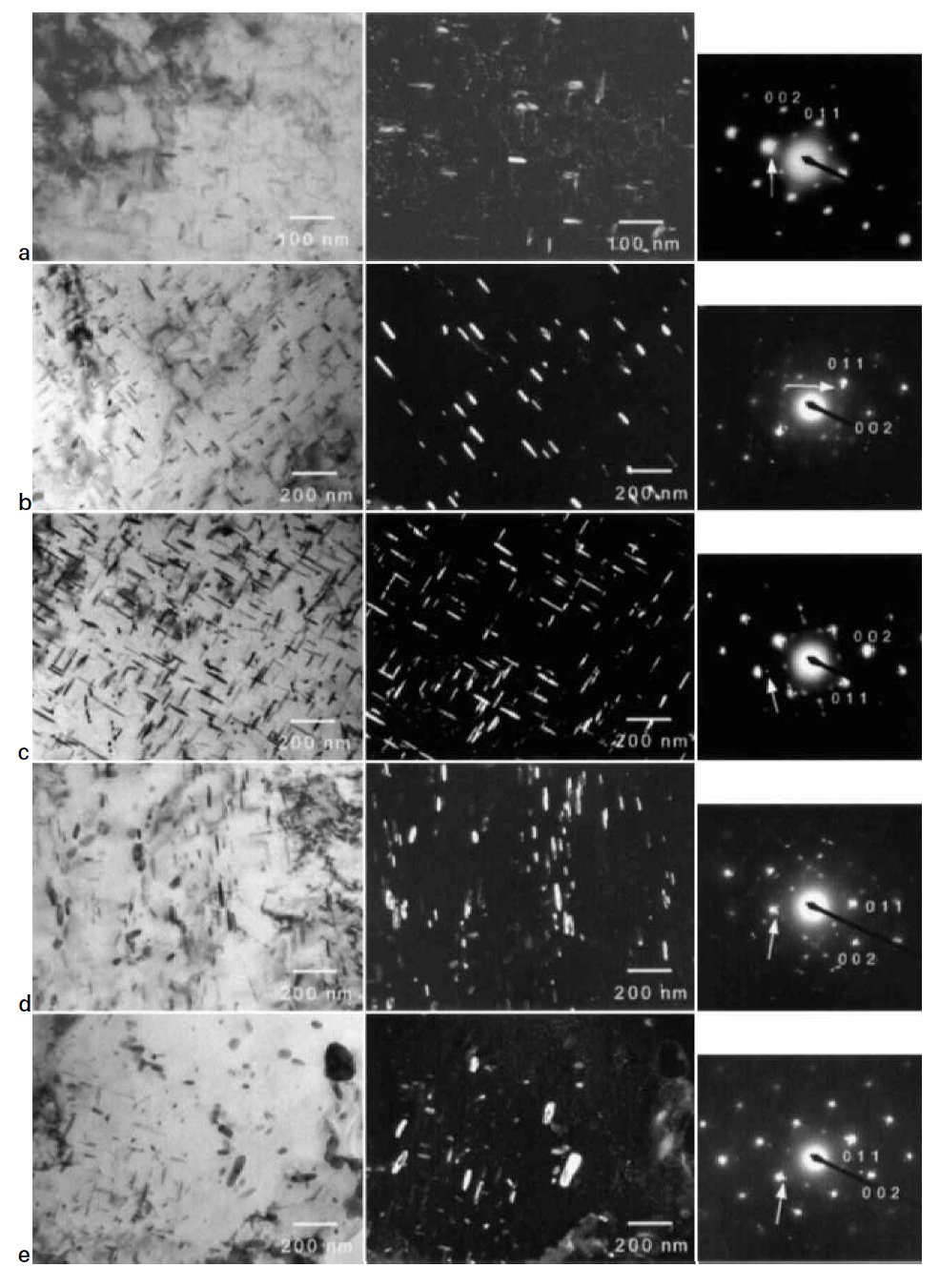
Figure 1: Observation (TEM) of test steel tempered at 600°C for different times: zone axis is [001] of ferrite; each dark fieeld
image was taken using diffraction spot indicated by arrow. (a 10 h; b 30 h; c 100 h; d 560 h; e 1160 h). Scale bars: 200 nm.
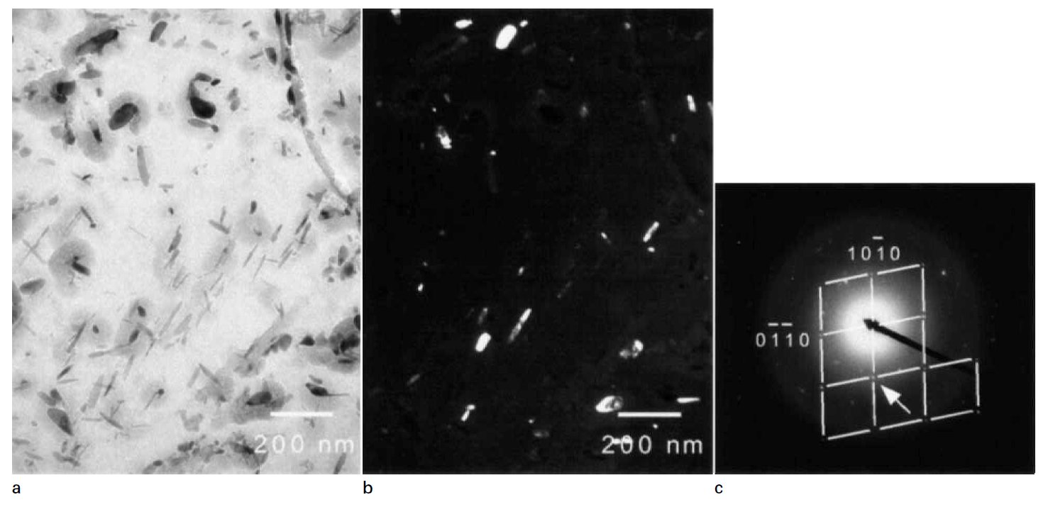
Figure 2: Observation (TEM) of extraction carbon replica specimen from steel tempered at 600°C for 560 h: precipitates are M2C. (b is dark field image of diffraction spot indicated by arrow in c). Scale bars: 200 nm.
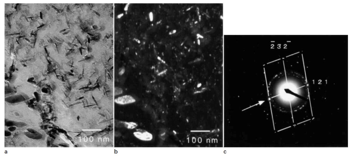
Figure 3: Observation (TEM) of extraction carbon replica specimen from steel tempered at 600°C for 10 h: precipitates are
cementite. (b is dark field image of diffraction spot indicated by arrow in c). Scale bars: 100 nm.
Carbide name: Mo2C, Fe3C
Record No.: 1010
Carbide formula: Mo2C, Fe3C
Carbide type: M2C, M3C
Carbide composition in weight %: No data
Image type: TEM
Steel name: FeCMo martensitic steel
Mat.No. (Wr.Nr.) designation: No data
DIN designation: No data
AISI/SAE/ASTM designation: No data
Other designation: No data
Steel group: Martensitic steels
Steel composition in weight %: Fe 0.10C<0005Si 1.99Mn1.60Mo 0.03Al 0.0049N (wt-%).
Heat treatment/condition: The steel was vacuum melted as a 10 kg ingot, heated at
1250°C for 30 min in an argon atmosphere, hot rolled to
12 mm thickness plate and air cooled. From this plate, the
specimens for heat treatment were machined to 3 and 8 mm
diameter. The specimens were sealed in silica tubes under a
partial pressure of argon (~150 mm Hg), before normalising.
According to equilibrium calculation using MTDATA,
the steel should be fully austenitic at temperatures above
1000°C. The homogenisation temperature was therefore
chosen to be 1250°C, at which the specimens were held
for 50 h.
After the homogenisation treatment, the specimens were
quenched into water and the silica tubes were broken. Then,
specimens were sealed again and tempered at 600°C from
0.5 1160 h. After tempering, all specimens were again
quenched into water, breaking the silica tube.
Note: The precipitation and Ostwald ripening behaviour of needle shaped Mo2C particles during the tempering of a
ternary FeCMo martensitic steel have been characterised and modelled, taking account of local equilibrium, the
capillarity effect, and the simultaneous enrichment and dissolution of cementite. Particles of Mo2C are represented
as paraboloids of revolution, with the tip radius chosen to yield the maximum lengthening rate. Transmission
electron microscopy has been used to validate the theory; measurements of the average
The steel contains 0.1 wt-% carbon and a stoichiometric quantity of molybdenum
for Mo2C. As will be shown later, experimental data
and thermodynamic calculations show that in this steel
the carbide is virtually pure Mo2C with negligible quantities
of iron or manganese in the metal sites. Therefore, its
precipitation is modelled as if it occurs in a ternary Fe C
Mo system.
Molybdenum carbide: Figure 1 shows thin foil TEM images of the specimens
tempered for a variety of times. These pictures were taken
from the [001] orientation of the ferritic matrix. Figure 2
shows TEM images of a carbon replica specimen from the
steel tempered for 560 h. From the diffraction patterns in
Fig. 2, the needle shaped precipitates have a hexagonal
close packed (hcp) structure and are considered to be M2C,
where M stands for metal atoms (Mo, Mn, Fe). The
chemical compositions of M2C particles were measured
using energy dispersive spectroscopy using carbon replica
specimens; the average ratio of metallic elements is
0.91Mo: 0.06Mn: 0.02Fe. These precipitates are therefore
virtually pure Mo2C. It is known that Mo2C grows along
the three equivalent <001>alpha directions, and, for example
in Fig. 3, precipitates growing in three <001>alpha a directions
are observed. In Fig. 3, the point like precipitates are the
cross-section images of precipitates growing in the [001]
direction, which is parallel to the observation direction.
Cementite: Figure 3 shows an example of a carbon extraction replica
TEM image of the steel tempered at 600°C for 10 h. Cementite
particles precipitate on the prior austenite grain boundaries
and the martensite lath boundaries. Cementite particles are
also evident within the laths. Particles precipitating on the
boundaries are spheroidal or plate shaped and the average
thickness is 50 nm. On the other hand, the particles precipitating
within the laths are plate shaped and the average
thickness is 20 nm.Cementite in the laths dissolvedafter 100 h
tempering at 600°C, but it persisted on the grain boundaries.
Links: No data
Reference: S. Yamasaki and H. K. D. H. Bhadeshia, Modelling and characterisation of Mo2C
precipitation and cementite dissolution during
tempering of Fe CMo martensitic steel, Materials Science and Technology June 2003 Vol. 19, pp. 723-731.