Alphabetical Index
Browse by Elements
Keyword Search
Dry Etchants
Dry and Wet Etchants
Wet Etchants
Bulk Etchants
Layer Etchants
Nano Etchants
Single Crystal Etchants
Thin Film Etchants
Thin Foil Etchants
Wafer Etchants
Al Etchants
Cd Etchants
Ga Etchants
Ge Etchants
In Etchants
New Etchants
Other Etchants
Si Etchants
Zn Etchants
Help
Home
Sub-Surface Damage
Material Name: Silicon
Record No.: 103
Primary Chemical Element in Material: Si
Sample Type: Wafer
Uses: Etching
Etchant Name: None
Etching Method: Dry etching
Etchant (Electrolyte) Composition: No data
Procedure (Condition): No data
Note: All commercially available grinding systems use a two-step process including a coarse
grinding that performs the bulk of the material removal and a subsequent fine grinding.
The first grinding step is performed with a rough grinding wheel (small mesh) in order
to remove the bulk of the Si at high speed (in the order of a few ìm per second). Yet, it
causes deep SSD due to the brittle nature of the Si wafer in combination with the big
grit size. This damage layer is typically confined to the first 30-20 µm below the ground
surface (Fig 1). A fine grinding step is then performed to remove this damaged layer
created by the coarse grinding step and reduce surface roughness by means of grids with
smoothest roughness than that ones used for the first step. This step provides a mirror
like surface that is the final finish of the wafer backside.
Fine grinding step provide the highest wafer and die strength as the high grit wheel
removes the most subsurface damage. As a rule, as the grit increases, the wafer strength
and smoothness improves, while the wafer warpage and subsurface damage decreases.
However, there is a remaining defect band near the surface. Although the fine grinding
is used to remove the SSD from the rough grinding, it also introduces its own damage,
though in a much smaller range, normally a few microns deep or even below 1ìm.
The residual defects cause stress in the thinned wafer, leading to an additional bow and
often broken wafers during handling or further processing. This means that additional
thinning is necessary to remove the remaining defect layer and surface roughness after
mechanical grinding. This can be done by either chemical mechanical polishing (CMP),
dry etching (ADP) or wet chemical etching.
Reference: Isabella Para, Thermal dissipation improvement by new
technology approach: study, development and characterization, PHD Thesis, POLITECNICO DI TORINO, 2017, pp. 4-5.
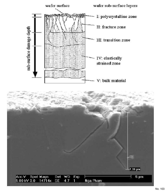
Figure 1: Sub-Surface Damage stack (top) and SEM image of cracks (fracture zone) introduced
because of the rough grinding process (bottom).