Alphabetical Index
Chemical Composition of Steels
Keyword Search
Steel Names
Alloyed Steels
Carbon Steels
Cast Irons
Chromium Steels
Cold Work Tool Steels
Creep Resistant Steels
Hot Work Tool Steels
Molybdenum Steels
PM steels
Stainless Steels
Structural Steels
Tool Steels
Vanadium Steels
White Cast Irons
M2C Carbides
M3C Carbides
M7C3 Carbides
M23C6 Carbides
MC Carbides
Light Microscopy
EDS/WDS Microanalysis
Scanning Electron Microscopy
Transmission Electron Microscopy
X-Ray Diffraction
Help
Contact Us
Home
Carbides in spray-formed AISI M3:2 high-speed steel

Figure 1: Microstructure of as-sprayed material (a) optical micrograph of polished
sample demonstrating the presence of a carbide network, (b) optical
micrograph of etched sample, (c) SEM image of etched sample. Scale bars: 50, 50, 5 µm.

Figure 2: Series of optical micrographs along compression axis of specimen
deformed in experiment C. Positions corresponding to (a)(d) are indicated
in Fig. 1. Scale bars: 50 µm.
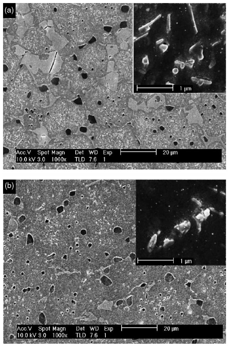
Figure 3: SEM images of cross-sections perpendicular to compression axis of
compression test samples (a) experiment B: nominal deformation temperature
900 C, (b) experiment H: nominal deformation temperature 1100 C.
Note the difference in density of submicron-sized carbides and the presence
of cracked carbides in (a). Scale bars: 20 µm.

Figure 4: Optical micrographs for specimens deformed at strain rates given
and nominal temperatures T = 900 C (a), T = 1000 C (b) and T = 1100 C (c). Scale bars: 25 µm.
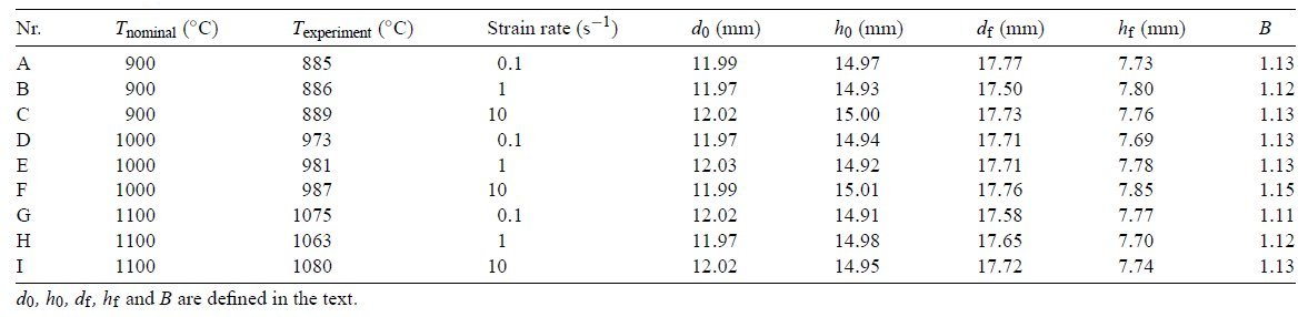
Table 1: Dimensions of specimens before and after deformation.
Carbide name: Carbides
Record No.: 733
Carbide formula: No data
Carbide type: No data
Carbide composition in weight %: No data
Image type: LM, SEM
Steel name: ASP 2024
Mat.No. (Wr.Nr.) designation: No data
DIN designation: No data
AISI/SAE/ASTM designation: AISI M3:2
Other designation: No data
Steel group: PM High speed steels
Steel composition in weight %: 1.31% C, 6.24% W, 5.34% Mo, 4.12% Cr, 3.05% V, 0.56% Si, 0.24% Mn, 0.11% Ni, 0.22% Cu, 749 ppm N.
Heat treatment/condition: A 3-ton spray-formed high-speed steel billet was supplied by Danspray (Gregersenvej 8, 2630 Taastrup, Denmark) in
the as-sprayed condition with approximate dimensions 0.5 wide by 2 m long. Axisymmetric compression tests at temperatures in
the range of 9001100 C and strain rates between 0.1 and 10 s-1 were carried out in order to simulate the microstructure
evolution during forging. The nominal maximum strain for all experiments was 0.69, which corresponds to a reduction
of 50%. This is a typical height reduction for billets to be forged into work rolls. The load was applied by means of ceramic platens with
an average temperature, as given in Table 1. There was a
temperature gradient between upper and lower platen e.g.
for a nominal test temperature of 1000 C, the temperatures
of the platens were 990 and 1010 C, respectively. The temperature
of the test specimen was measured by means of a
thermocouple in the centre of the specimen. The specimen
was heated by induction for 2 min to the required test temperature
and then held at that temperature for 1 min before
the compression test was started. After reduction of the specimen
to 50% of the original height, the test specimen was
removed from the furnace and water quenched. The time between
the end of deformation and onset of water quench was
about 1 s.
Note: Axisymmetric hot compression tests (9001100 C) on spray-formed AISI M3:2 high-speed steel were performed in order to establish
suitable parameters for hot forging of this material. Special attention was paid to establish the deformation conditions that lead to the
breakdown of the carbide network, present after spray forming, and to avoid fracture of the material as a result of deformation. By a
combination of microstructural analysis and finite element modelling, values for fracture stresses in this temperature range and critical strains
for the breakdown of the carbide network are given. The activation energy for hot deformation was also determined.
Influence of compression test parameters on microstructure: The initial microstructure of the as-sprayed material is
shown in Fig. 1 .As far as the carbide distribution is concerned three different length scales were present: I. Carbide network around 70 µm consisting of irregular
shaped carbides (highlighted by a black line in Fig. 1a), and close to elliptical or round carbides with average size of about 10 microns (marked by white lines in Fig. 1a); II. Close to elliptical or round carbides of micron size (examples marked by white circles in Fig. 1c); III. Rod shaped and rectangular carbides of sub micrometer size (Fig. 1c).
Carbides of category I and II were visible by optical microscopy
of polished samples (Fig. 1a). Carbides of group
III were only visible in SEM images (Fig. 1c). However, a
darkening in optical micrographs of the nital etched material
(Fig. 1b) is indicative of their presence. This can be seen by
comparing Fig. 1b and c. From these figures it is also evident
that the carbide density varies from cell to cell.
In order to investigate the influence of compression test
parameters on microstructure, these different length scales
have to be considered separately. The influence of strain on
the carbide network structure is shown in Fig. 2, which shows
a series of optical micrographs taken along the compression
axis of the test specimen. No deformation
of the cells is observed in Fig. 2a, taken from the area
in contact with the tool during compression. Moving towards
the centre of the specimen the carbide cell is first seen to be
deformed in Fig. 2b, and then only local remnants are observed
in Fig. 2c. There were no indications for the presence
of a carbide network in the centre of the specimen (Fig. 2d).
This behaviour was observed for all tests and indicates that
the carbide network is broken down by deformation amounting
to an equivalent plastic strain between 0.82 and 0.89,
depending on deformation temperature.
A higher
deformation temperature resulted in a slightly lower critical
strain. The deformation temperature influences the carbide
network in the direction perpendicular to the compression
axis. The cracking of large irregular-shaped carbides was observed
for deformation at 900 C (Fig. 3a) but not at 1100 C (Fig. 3b).
The number of carbides of category III strongly depends
on the deformation temperature, as is evident by comparing
Fig. 3a and b. In these figures, the small carbides are represented by the small white dots in the low-magnification
SEM images. The low magnification was chosen to provide
a better impression of the density distribution over a large
area, whereas the insets demonstrate the actual shape and size of the type III carbides. The high density of carbides at the
lower deformation temperature of 900 C in Fig. 3a is apparent. A low carbide density in conjunction with a strong local
density variation was observed for deformation at 1100 C (Fig. 3b).
The deformation temperature also influences the structure
of the matrix, as can be seen from Fig. 4. For deformation
below 1100 C (Fig. 4a and b), the matrix grain boundaries
were not revealed by nital etching. However, following deformation
at 1100 C, a well-developed matrix grain structure,
resembling a recrystallised structure, was observed (Fig. 4c).
However, recrystallisation did not seem to have taken place
homogenously, and was only observed in the bands of lower
carbide density (represented by absence of small black dots)
in Fig. 4c.
Links: No data
Reference: Not shown in this demo version.